|
HOME
WHAT'S NEW
CLUB
MEMBERS
EVENTS
ARTICLES
GALLERY
FORUM
LINKS
SITE MAP
|
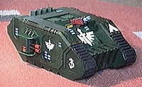
When I first saw the new MkIII Landraider I knew
that I wanted one (or more) for my Space Marine army. However my financial
situation did not allow me to outlay the £30 asked.
A while ago I came across a site which gave the
plans for building various 40K vehicles out of only paper and card, and
on checking back I found that there were plans for the Landraider MkIII.
There is very little in the way of instructions,
however I persevered and finally got one built. There are a few things
I discovered during this exercise and so I have decided to write this
tutorial for building one of these paper monsters.
What you will need
- The first thing you will need are the files from the
BWC-Archive.
|
landr1.gif
|
Land Raider tracks |
|
landr2.gif
|
Land Raider side armorplates |
|
landr3.gif
|
Land Raider main hull |
|
landr4.gif
|
Land Raider weapons + additional parts |
- Printer
- Craft Knife
- Steel Rule (or other straight metal edge)
- Cutting mat (so you don't ruin the kitchen table)
- PVA Glue
- Green Stuff or Fine filler
- 4 sheets of A4 0.8mm thick card (cereal packet thickness)
- 2 sheets of A4 1.0mm - 1.5mm thick card (Matt board
- used in picture mounting or use the backs of note pads)
- Patience - most important of all :)
Printing the Plans
All the files you have downloaded need to be printed
to the correct scale (190mm wide x 270mm high) most graphics programs
will allow you to state the size you want print (once you have printed
them measure the outside borders to ensure they are the correct size)
|
landr1.gif
|
Print twice on 0.8mm card |
|
landr2.gif
|
Print once on 1.0mm-1.5mm card |
|
landr3.gif
|
Print once on 0.8mm card |
|
landr4.gif
|
Print once on 0.8mm card |
Your printer may have a problem printing on card,
so there is another way you can do it. Print all the plans on normal A4
paper (remember to print landr1.gif twice), then glue them to the card
using the PVA glue. Ensure that you cover the paper totally or else when
you cut out the pieces the paper will peel. Stack some heavy books on
the sheets until the glue dries
Some of the parts on landr4.gif need to
be made from the thickest card. These are all marked with letters (Capital
and lowercase) plus the tracks, track treads and hatches (these should
be marked O - S but are not). Use the same procedure as above but cut
roughly around the pieces and stick them onto the thicker card rather
than sticking the whole sheet down.
Creating the Folds
To ease the construction of the model score each
of the creases with the craft knife, being careful not to cut through
the card. Use a steel rule or other suitable straight edge or else the
folds will be crooked.
Assembly
I would recommend that you only cut out the parts as you
need them or else you will easily get lost.
- Track Assembly. Glue 1a to 1b where
indicated then attach this to 1c, glue in the two strengthening
supports (1d) and finally glue the other 1c into position.
- Repeat this for the other Track Assembly.
- Hull. Assemble parts 2a to 2d
in the same way.
- Glue A onto the Track Assembly and then glue
B on top of that by aligning the top slots with each other, they
should be flush at the top (see diagram 1).
- Glue C and D to the top of the tracks
(D being on the top) aligned with the grooves of A+B and flush
with the opposite side of the assembly.
- Glue E and F to the front of the Track
Assembly.
- Glue G and H to the rear of the Track
Assembly.
- Repeat iv - vii
for the other Track
 Assembly,
make sure that you make the opposite side. Assembly,
make sure that you make the opposite side.
- Glue I and J to the top of the Hull in
the same way (see diagram 2).
- Glue K and L onto the back of the Hull,
aligning the slots with I + J.
- There are some unmarked details on landr2.gif that
need to be cut out and attached, refer to diagram 1 for details.
- Using Green Stuff, Filler or something similar, create
the 45° chamfers on the edges of the Track Assembly and the Hull.
Take your time over this and make them as neat as possible. Once dry,
you can use a knife or file to clean them up.
- Glue the Track Assemblies and the Hull together align
C+D with I+J at the back (see Diagram 2).
- Exhaust Box. Glue together 3 and glue
this underneath K+L on the back of the Hull.
- Exhaust Pipes. Glue together 4a and 4d to create
the 4 Exhaust Pipes.
- Glue the Exhaust Pipes onto the exhaust box. I tried
gluing them to the places indicated, however they were too weak so I
glued them together diagonally and them glued them to the Exhaust Box.
- The next part you need to cut out is 5, but
note that there are no tags to attach the piece to the model,
by this time you should understand how the tags work, so draw on some
tags yourself before you cut it out. Glue this to the front (sloped)
part of the Hull (see Diagram 2)
- Front Doors. Glue M and N to the
front of the Hull as shown in Diagram 2
- Tracks. Cut out and crease O. Cut up P then
glue P onto O as indicated (although the track marks are not shown completely,
the entire track section should have the treads attached).
- Glue the Tracks onto the front and rear of the Track
Assemblies (see Diagram 2).
- Glue Q R and S together (Q at
the bottom, S at the top) and then glue these on
 top
of the Hull (see Diagram 2) top
of the Hull (see Diagram 2)
- Side Sponsons. Glue together parts a
to d as shown in Diagram 3 (opposite) these are quite fiddly,
and the pieces will get stuck to your fingers. Using a pair of tweezers
helps (especially for d)
- Las-Cannon Body. Assemble 6, and glue
on e to h as per Diagram 3
- There are three square pieces (next to d on landr4.gif)
you will need two of these for each Las-Cannon Body. Glue one on the
Top on bottom of the Las-Cannon Body(6)
- Gun Barrels. Cut a 2.5cm strip of normal typing
paper and roll it it up to form the gun barrels (it is up to you as
to the diameter). then roll a 6mm wide strip of paper around the end
to form the end of the gun barrels. You will need 2 of these.
- Las-Cannon. Glue the gun Barrels to the Las-Cannon
Body and then glue the entire Las-Cannon into the Side Sponsons as shown
in Diagram 3.
- Repeat xxii - xxvi
for the other Side Sponson.
- Glue the Side Sponson Assemblies onto the Track Assemblies
as shown in Diagram 1.
That's about it, there are other details you can
add to the model, like the insignia that attaches to part 5, but
these are up to you.
All that is left now is to paint.
Why don't you have a go, it's not as difficult
as you might think.
I will be building another Landraider, and when
I do I will take stage photos to help illustrate this article.
If this article is popular, then I may well produce
one for some of the other models, let me know what you think.
Bile's site had plans for other vehicles including
a Rhino, Predator Destructor, Whirlwind, Land Speeder, the old MkI (Rougue
Trader) Land Raider and a Cybot (Dreadnought).
After writing this article Biles site closed, as
such I started a Yahoo! Group and uploaded all the plans I had to the
files section. To get the gifs needed for this article (and any of the
others) just join the BWC-Archive and navigate to the Files Section. At
the time of writing all the above plans are there plus some I.G. tanks
and colour chapter versions of the Rhino.

Click to subscribe to BWC-Archive
|
Note
The illustrations shown here are taken from Biles
site.
|